What is temperature-induced image drift in cameras?
In the field of optical engineering, cameras are essential tools used in areas such as machine vision, autonomous vehicles, medical imaging, and security systems. Their precision depends not only on advanced technology but also on the stability of the environment in which they operate. One of the biggest challenges in this regard is thermal image drift, a phenomenon that can significantly disrupt even the most advanced measurement systems.
What is Thermal Image Drift?
Thermal image drift refers to the displacement of pixels in an image captured by a camera, caused by changes in temperature. Imagine a camera observing a stationary object—such as a simple pattern of black dots on a white background. In ideal conditions, each dot would always appear in the same place on the image. However, in practice, as the temperature rises or falls, the image begins to “drift,” shifting its position at sub-pixel or even pixel levels.
This phenomenon results from two primary factors:
• Camera warming-up process – Cameras, especially those used in industrial settings, generate heat, which deforms their internal components, such as the image sensor, lens, or housing. This effect is most pronounced when the camera is turned on and gradually diminishes as it reaches thermal equilibrium.
• Changes in ambient temperature – Variations in the surrounding temperature similarly cause deformation of the camera’s structures and components. Depending on the amplitude and speed of these changes, the deformations can be minor or significant.
Why is Thermal Drift a Problem?
The biggest challenge in addressing thermal drift is its random nature. Even if the camera returns to its initial temperature, the points in the image may not align with their original positions. This means that standard compensation methods—based on predictable patterns—are ineffective in eliminating thermal image drift.
How Does Drift Appear in Practice?
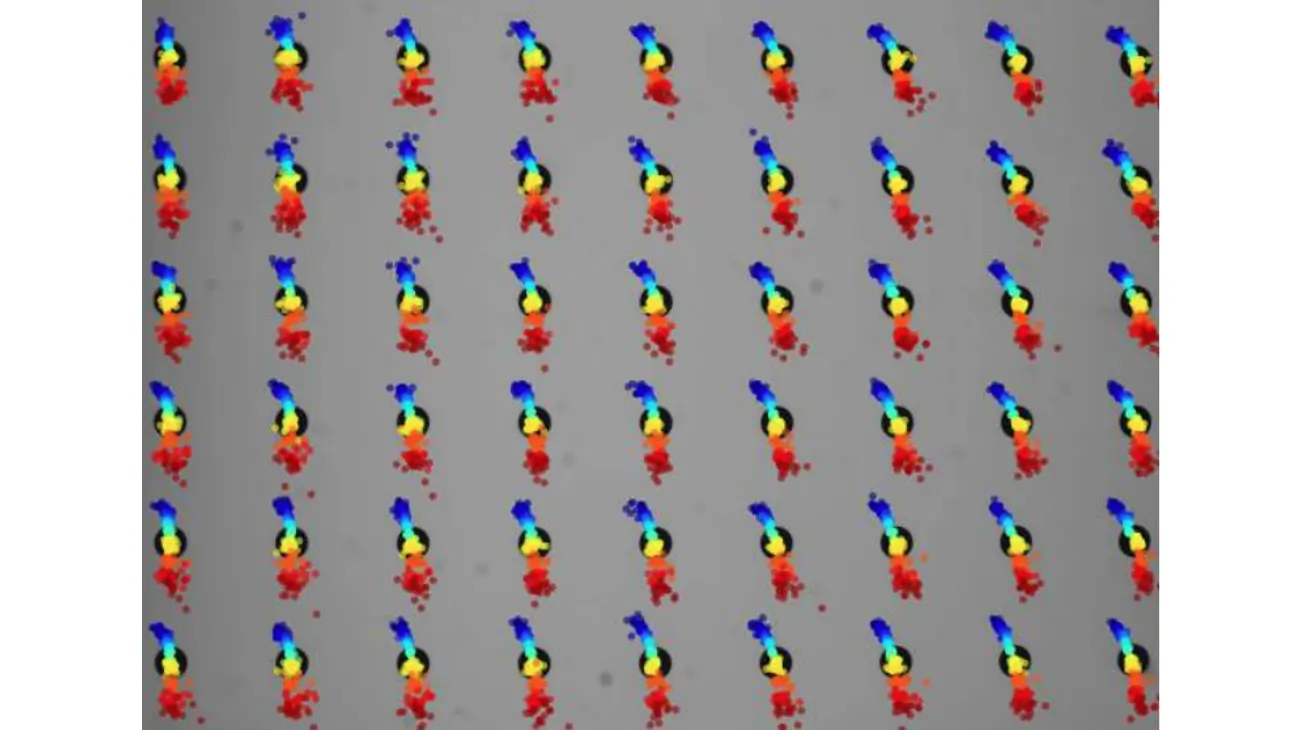
This phenomenon has been observed in numerous experiments. For example, in a study described in the article, during the warming-up process of a camera to a stable temperature, the positions of image markers shifted unpredictably. The trajectories of these points in two different experiments are shown in Fig. 1. Despite identical starting conditions, each heating cycle yielded different results.
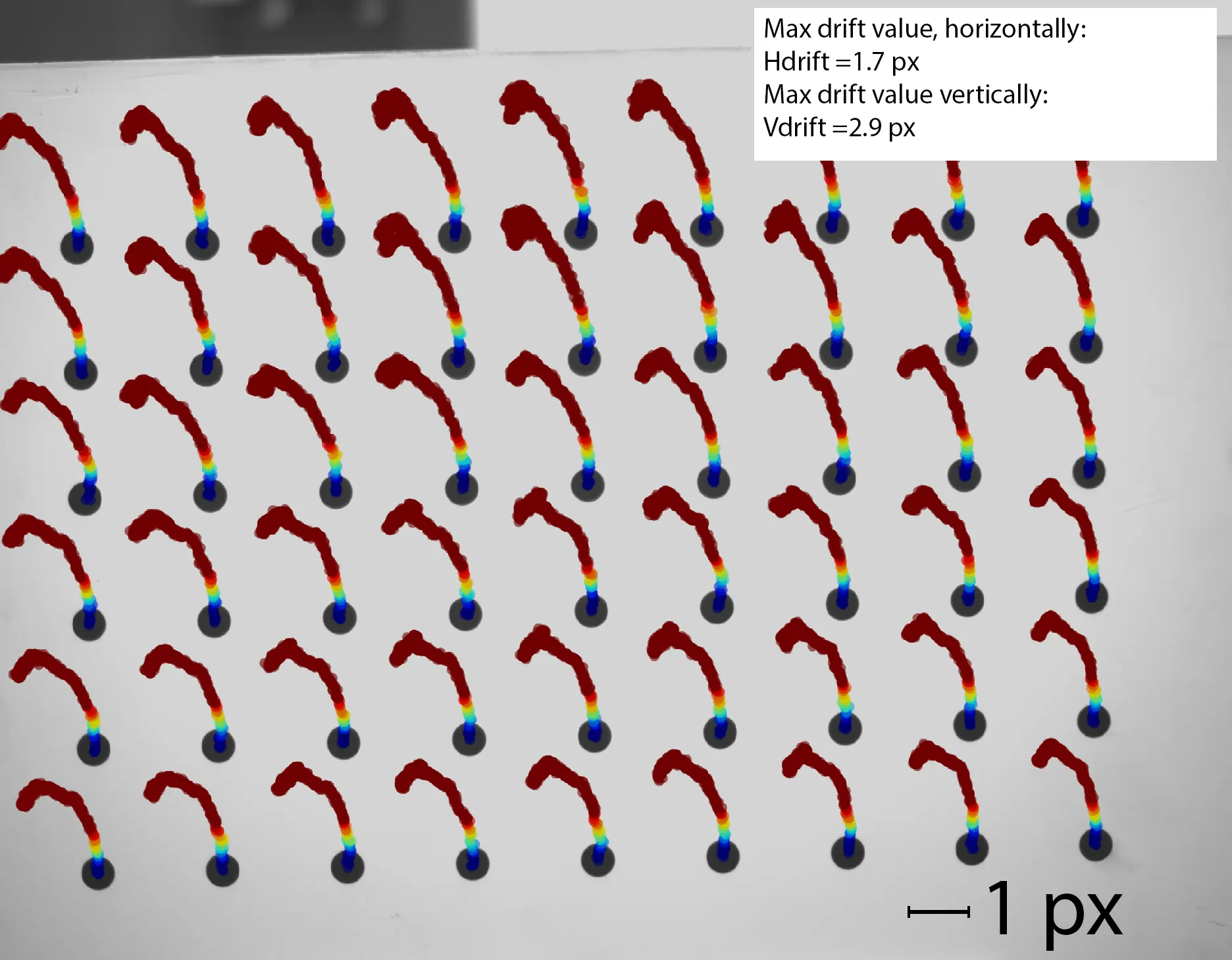
Fig. 1a
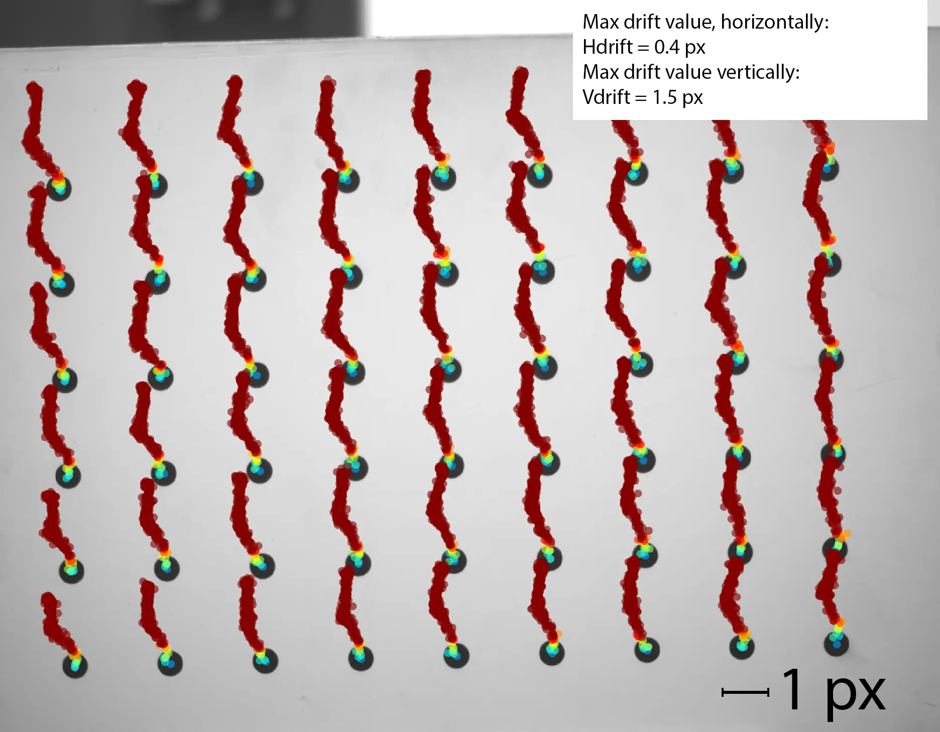
Fig. 1b
Fig. 1: Thermal image drift observed during two experiments with the warming-up process of the IDS UJ-6280SE-M-GL-R3 camera. After each experiment, the camera was cooled down. The background of each image represents the first captured frame. Colored dots (blue for the lowest temperature of 24°C and red for the highest of 45°C) indicate the successive positions of the calculated marker centers. The coordinate shifts were magnified 100 times for better visibility. Source.
What Causes Randomness?
In typical industrial cameras, the image sensor is rigidly mounted to the housing using threaded connections. This design means that during temperature changes, the sensor has no freedom to move and experiences mechanical stress. When the forces from thermal expansion exceed the friction between the screws and mounting, the sensor can shift. Unfortunately, these shifts are random and depend on factors such as screw tightness or material properties.
This mechanism is illustrated in detail in Fig. 2, which shows how stress in mechanical components can lead to uncontrolled movements of the sensor.
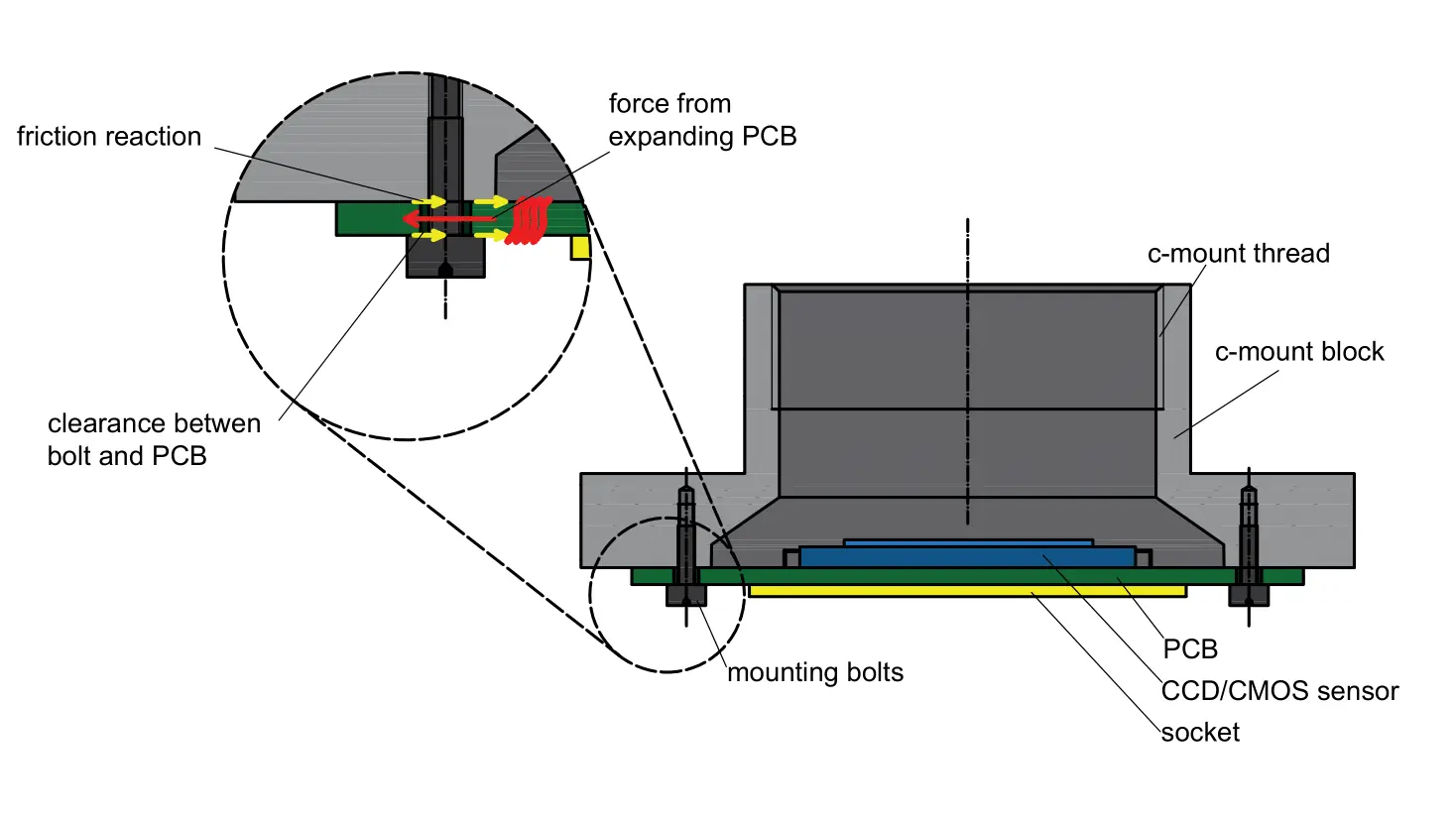
Fig. 2: Cause of thermal image drift: The printed circuit board (green) with the sensor (blue) expands due to rising temperature (warming-up or ambient temperature change). The lack of freedom for the board to move causes it to deform, as friction (yellow) between the screws (dark gray), board, and mount blocks its movement. When the expansion forces (red) exceed friction, the sensor shifts unpredictably. Source.
Why Does This Matter?
For users of cameras in measurement applications (industrial, medical, or research), even the smallest image shifts can lead to errors in data analysis. For instance, in machine vision systems used in precision robotics, where the margin of error is minimal, thermal drift can cause incorrect positioning of a robot.
In medical systems such as optical tomography, image shifts can impact diagnostic accuracy. This makes thermal drift not only a technical challenge but also a practical limitation in many critical fields.
Can Anything Be Done?
Although compensating for thermal drift is challenging, solutions do exist. One approach is to use athermalized technology, which introduces modifications to the camera’s optomechanical structure. These modifications significantly reduce thermal stress and eliminate the random nature of thermal image drift. If you want to learn more about thermal drift and compensation methods, feel free to read the full article or contact us.